RAL10AP TOTAL-POWER MICROWAVE RADIOMETER
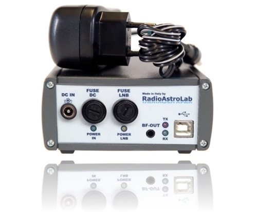
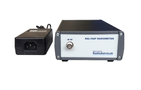
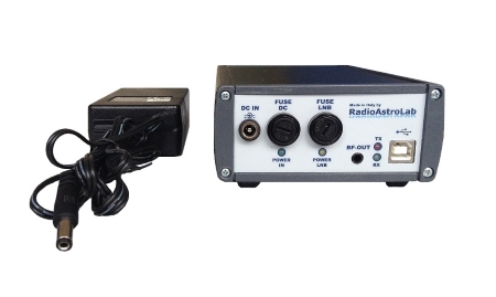
Working with RAL10AP is very simple: you need an antenna with its feed and LNB (Low Noise Block Converter) adapted to chosen receiving frequency (10-12 GHz Ku-band, 3-4.5 GHz C-band or directly in the 1390-1440 MHz input band), a 75 Ω TV-SAT coaxial cable that carries the signal to the receiver, an external 12 V power supply and a PC on which is installed the management software supplied by us. When everything is ready, you can connect the RAL10AP to the PC via a USB cable, the software starts and the measurement session begins.
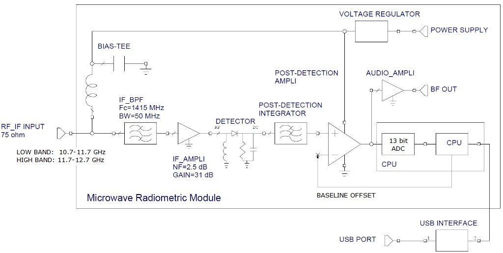
The following diagram shows the internal structure of RAL10AP. It is always possible to use LNB (and its antenna) with any input frequency, as long as the output frequencies are comprised in the receiving “window” accepted by the receiver (1390 to 1440 MHz).
The filter at the input defines the form of bandwidth, and protects against interference, maintaining the possibility to receive the “magic” frequency of the hydrogen at 1420 MHz.
The receiver amplifies and measures the received signal strength and, via an analog-digital converter (ADC) with high resolution, it converts the detected signal into digital form, by positioning the level of “zero” in the appropriate point of the scale. The critical functions of the receiver, as well as the possibility to set various operating parameters and communication with the PC via the USB interface module, are handled by the processor, to the benefit of the economy, compactness and accuracy in the measurement. To optimize the sensitivity of the system, you can integrate the detected signal with a programmable time constant.
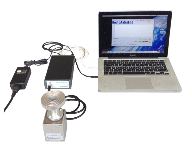
Here is a sample of the constituents involved (beside the antenna, which doesn’t appear in the picture …) in the making of an 11.2 GHz amateur radio telescope with RAL10AP: outdoor unit RAL10_LNB (thermo stabilized) with feed for circular parabolic reflector antennas, RAL10AP receiver with power supply and computer station for the control of the radio telescope and for the acquisition of the measurements.
Further analysis on the audio signal of post-revelation are possible by connecting the BF-OUT output (with a standard stereo audio cable equipped with 3.5 mm mini-jack connectors) to the input of the PC sound card, which also allows you to listen the ” revealed noise”. The following image shows some examples of audio output use, also useful for identifying possible artificial interference.
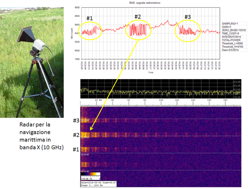
Test recordings made with RAL10AP and external unit RAL10_LNB equipped with an truncated pyramid horn antenna (20 dB gain), positioned on a camera tripod. The RAL10_LNB output was connected to the RAL10AP receiver with a coaxial cable. A portable PC records the radiometric signal at 11.2 GHz receiving data from the USB port through our acquisition software (upper panel) while is simultaneously recorded the audio signal from the output BF OUT of the RAL10AP, displayed as a spectrogram by the software Spectrum Lab (http://www.qsl.net/dl4yhf/spectra1.html). The records show the X-band radar signals of the boats when the antenna is oriented towards the sea.
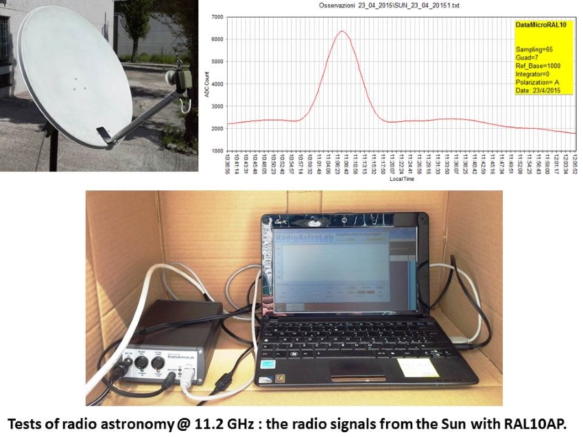
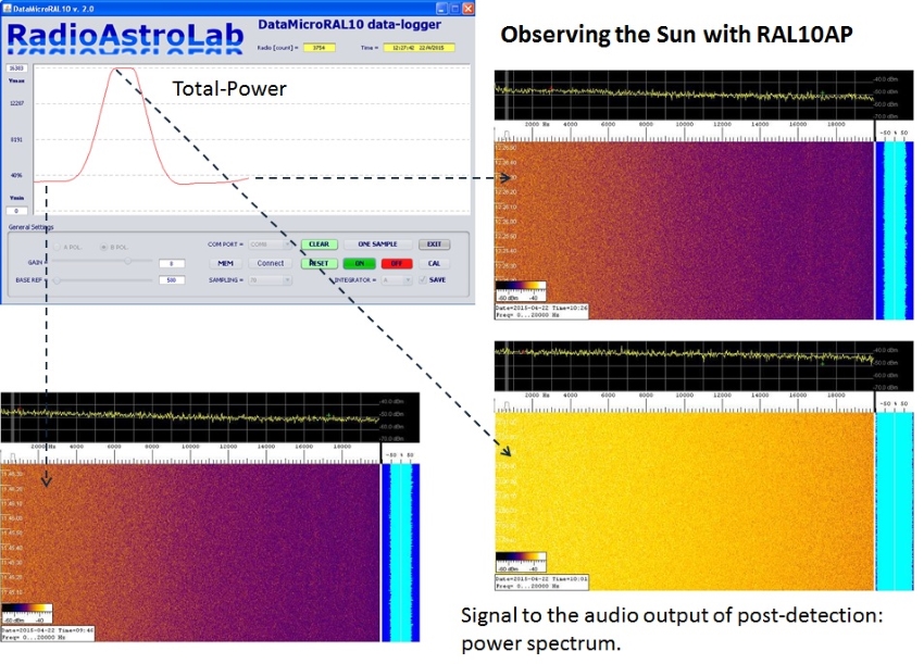
Registration of a solar transit with RAL10AP. Two recordings were acquired at the same time, with different acquisition software: the main radiometric observation (recorded with the provided software for the management of RAL10AP) highlights the classic track “bell” which documents the transit of the solar disk by antenna main lobe, spectrograms show how the distribution frequency of the signal revealed varies during the transit of the radio source. You can notice the background noise increase due to continuous spectrum radiation of the thermal emission of the Sun during the various phases of the transit. Through the PC speakers you can also listen to the corresponding increase in audio noise.
As already mentioned, with RAL10AP is possible to build a radio telescope that operates directly in the frequency band accepted by our receiver, without using frequency converters (LNB), but a chain of low noise amplifiers and bandpass filters which realize a receiver in direct amplification. Of course, taking into account the antenna used, it is necessary to ensure sufficient amplification for a correct detection of the received signal, together with a suitable filtering to minimize interference within the reception “window”.
An example of such constrictive “philosophy” is represented by the following radio telescope operating in a reception band that includes the “magic” frequency 1420 MHz of neutral hydrogen emission.
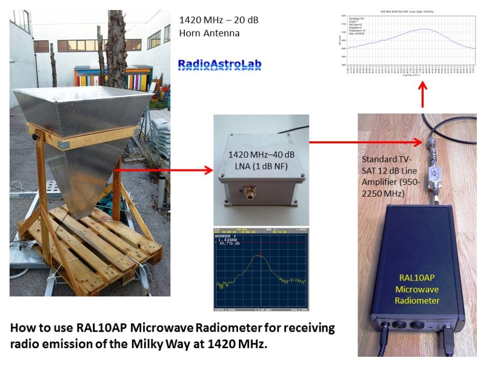
Example of receiver with direct amplification built “around” the radiometer RAL10AP. An horn antenna (20 dB gain) was used, together with a low noise amplifier (LNA) with band-pass filter centered on the frequency of 1420 MHz (connected immediately after the antenna), 30 meters of coaxial cable that carries the signal within the station. Before connecting the cable to the receiver RAL10AP a commercial line amplifier for TV-SAT is included.
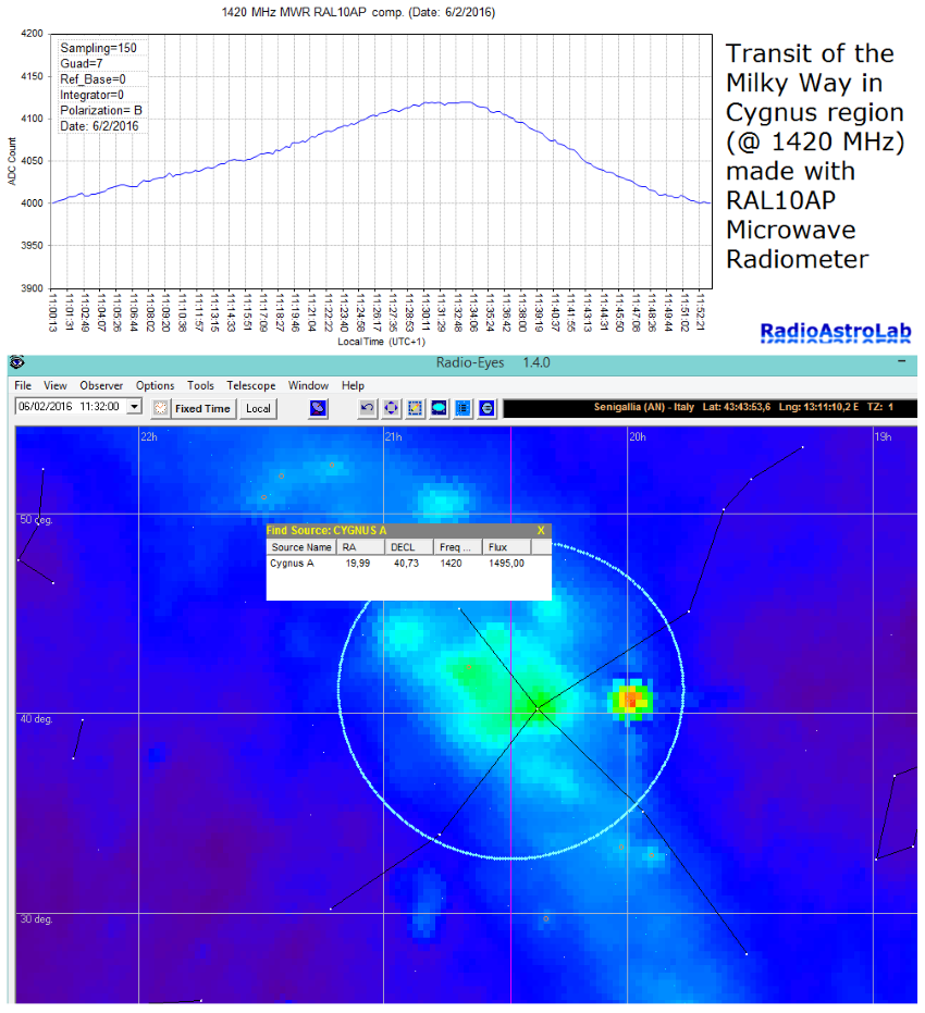
Transit of the Milky Way (Cygnus region) carried out with an experimental radio telescope based on RAL10AP receiver. The system reveals the radio emission of the galaxy at 1415 MHz (with a theoretical bandwidth of 50 MHz). The radiation includes the continuous component and the neutral hydrogen contribution to 1420.406 MHz, which falls into the “receive window” of the radio telescope. This record does not show the profile of the neutral hydrogen line, but the continuous emission of the Galaxy and the radio source Cygnus A unresolved because of the wide “field of view” of the antenna (around 16°).
RAL10AP Technical features
- Dimensions: about [105L, 50H, 138P] mm.
- Weight: about 0.545 kg
- Input centre frequency RF-IF: 1415 MHz.
- Bandwidth: 50 MHz.
- Typical section gain RF-IF: 20 dB.
- Input impedance (F-type connector): 75 Ω.
- Polarization selection (horizontal or vertical).
- Selection of the LNB reception band (LOW BAND – HIGH BAND).
- Temperature compensated quadratic detector (measurement of RF power).
- Setting the offset for the radiometric baseline.
- Automatic calibration of the radiometric baseline.
- Programmable post-detection voltage gain: from 42 to 1008 in 10 steps.
- Programmable integration constant (from 0.1 seconds up to 26 seconds).
- Acquisition of the radiometric signal with 13-bit ADC.
- Processor that controls the receiving system and manages the serial communication.
- Storage of radiometer parameters (internal non-volatile memory).
- USB interface (type B connector) for connection to PC.
- Compatible with ARIES acquisition and control software.
- Supply voltages: 7-12 VDC / 50 mA.
- Power supply for LNB through coaxial cable, protected with internal fuse.
Amateur radio astronomy: building a microwave radio telescope with RAL10AP

